


Important: Analysis of common causes of welding failures based on customer feedback
Failure Case: Welding the LED tubes first, then building the frame, and finally welding the PCB board connection pads. Not following the instructions can lead to the following problems:
Problem 1: This can damage the LED tubes.
Reason: LED tubes are not resistant to high temperatures. The PCB board connection pads are close to the LED tubes. When you weld the PCB board connection pads, the high temperature of the soldering iron can easily damage the LED tubes. To avoid this problem, you must weld quickly enough or follow the instructions.
Problem 2: Missing LED tubes.
Reason: The top layer requires 4 LED tubes, the bottom layer requires 4 LED tubes, and the middle layer requires 4 LED tubes. Some customers did not read the instructions and mistakenly thought the middle layer required 8 tubes. This results in a shortage of LED tubes.
LED Tube Properties: This is a hard ceramic tube, which is not resistant to force; bending will damage the tube. Please be careful when soldering. The light-emitting part of the ceramic tube is not resistant to high temperatures.
Making this kit requires some basic soldering skills. If you are a beginner, please ask an experienced friend to guide you through the soldering process.
Before assembling the product, it is recommended to watch the installation video provided by the link to your purchased product. Then, read the product manual.
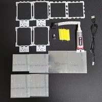
1. Rubber bands can be used to assist in building the product framework.
2. All PCB board resistor pads, ceramic lamp pads, and PCB board connection pads should face inwards.
3. After the framework is built, adjust the gaps between the PCBs to be as small as possible.
4. After confirming that the assembly is correct, apply glue to the eight corners inside the product. Wait for the glue to harden, which should take 3 to 4 hours.
5. Use scissors to cut off the rubber band that cannot be removed.
6. Soldering is used to connect the 24 pads on the PCB board, 12 on top and 12 on the bottom, making the product frame more robust.
7. Welding resistance
9. Solder the DC power connector and switch.
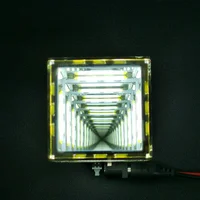
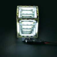
10. Power supply voltage DC5V
11. Power on and check if all 12 lights are lit. If the lights are not lit, please check for issues such as poor soldering, incorrect soldering of ceramic lamps, and whether the product is receiving power. Please do not suspect a problem with the circuit design.
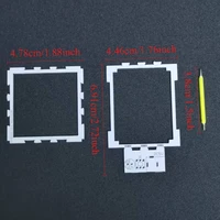
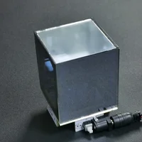
12. Attach the acrylic semi-transparent mirrors. The bottom acrylic semi-transparent mirror is 44.2*44.2mm, the top one is 47.5*47.5mm, the front and back are 57.6*47.5mm, and the left and right are 57.6*50mm. After determining the position of each acrylic semi-transparent mirror, peel off the blue protective film and glue the acrylic semi-transparent mirror to the PCB board.
13. Secure the acrylic semi-transparent mirror on the side with a rubber band to prevent it from falling off.
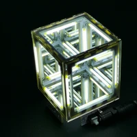
14. After the glue has hardened, remove the rubber band. Peel off the transparent protective film, and your electronic DIY project is complete.
e.


Reviews
Clear filtersThere are no reviews yet.